

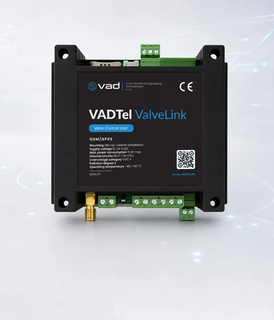
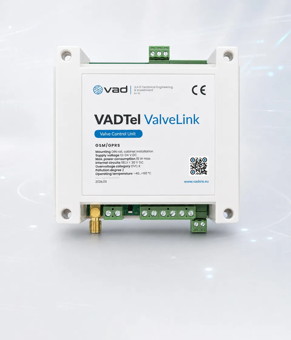
Valve-control unit
VADTel ValveLink
Remote valve control unit for utility shutoff, enabling fast remote response from the VAD IIoT Platform.
- Remote valve control over GPRS / NB-IoT cellular
- Four switched outputs for compressor and pneumatic manifold
- Isolated RS-485 acquisition from meters, correctors & calculators
- Cabinet tamper and actuator stem-position supervision
- Conformity
-
EU Declaration of Conformity
- Lifecycle
-
WEEE disposal & traceability
- Application class
-
Non-Ex cabinet installation
-
Remote valve control
Drive the compressor and pneumatic manifold and issue open/close commands from the VAD IIoT Platform over cellular — response in minutes rather than hours.
-
Metering-node integration
Polls compatible RS-485 meters, correctors and calculators for live values, archives, configuration data and events — one cabinet node for telemetry and control.
-
Cabinet supervision
Monitors the cabinet tamper contact and actuator stem position, with an audit-grade log of every valve state change reported to the platform.
-
Field-ready form factor
DIN-rail enclosure, 12–24 V DC supply and −40…+60 °C operation, engineered for unattended utility cabinets in gas, water and heat nodes.
-
Diagnostics & service history
Tracks valve-drive health, limit-switch status and response time, with full maintenance and service-history records on the platform.
VADTel ValveLink is the cabinet-level node of the VADTel telemetry stack. It combines cellular communication, isolated RS-485 acquisition from compatible external metering devices, cabinet tamper supervision, actuator-position interfacing and dedicated outputs for pneumatic-manifold and compressor control — all in a single DIN-rail device sized for 12–24 V DC utility cabinets.
The controller acts as the link between the local valve assembly, the metering devices and the supervisory backend. It polls compatible meters over RS-485, supervises cabinet-level status, drives the valve equipment according to project logic, and reports telemetry through GPRS / NB-IoT communication.
Where it fits
- Gas — metering nodes with remote shutoff, gas volume correctors and cabinet telemetry.
- Water — distribution chambers and metering cabinets with automated valves and compatible RS-485 metering.
- Heat — heat calculators, valve stations and district-heating substations with cabinet-level telemetry.
Control & telemetry workflow
- Poll meters — read current values, archives and events from compatible RS-485 devices.
- Monitor local state — supervise the cabinet tamper input, actuator stem position and cabinet-level status.
- Control valve equipment — drive the compressor and pneumatic manifold through the four switched outputs according to project logic.
- Report telemetry — send telemetry and event data to the supervisory system over cellular communication.
Cabinet-level architecture
A typical installation pairs ValveLink with a 12/24 V supply or battery-backed cabinet power, a GSM antenna, a cabinet door switch, a compressor and pneumatic manifold, an actuator-position board and a pneumatic actuator on the valve stem. On the metering side it connects to compatible resource meters, gas volume correctors, water meters, heat calculators and other RS-485 devices. Pressure sensing and the final electrical implementation depend on the project variant and wiring documentation.
Managed from the VAD IIoT Platform
The cloud-based IIoT Ecosystem turns the cabinet node into a fully supervised asset:
- Remote valve control — open / close — through cellular communication.
- Real-time device status monitoring and communication-session tracking.
- A management log with a full audit trail of valve state changes.
- Device diagnostics: valve-drive health, limit-switch status and response time.
- Service history with maintenance records, job types and executor tracking.
Combined with VADTel Sens for pressure monitoring and an IIoTU3 or AIIoTU8 module for connectivity, ValveLink forms a complete remote-shutoff loop — a key building block for utilities working under the EU Methane Regulation and similar safety frameworks.
Full documentation — product passport, technical specifications, EU declaration of conformity and installation instructions — is available on the IoT documentation portal.
| Power & safety | |
|---|---|
| Mounting | DIN rail, cabinet installation |
| Supply voltage | 12–24 V DC |
| Max power consumption | 15 W |
| Internal circuits | SELV < 30 V DC |
| Overvoltage category | OVC II |
| Pollution degree | 2 |
| Operating temperature | −40 °C to +60 °C |
| Control outputs | |
| OUT1–OUT3 | 3 outputs, 12/24 V DC, 5 A max each |
| OUT4 | 1 output, 12/24 V DC, 10 A max |
| Inductive loads | External suppression required |
| Inputs & local interfaces | |
| Tamper input (IN-TAMPER) | Dry contact, 1 input |
| Position sense (POS-SENSE) | 3-wire, 3.0–4.2 V DC |
| I²C | 3.3 V logic |
| Communications | |
| Cellular | GPRS / NB-IoT (LTE Cat-NB1 / NB2) |
| RS-485 | 1 isolated port, A/B |
| RS-485 signal level | 1.5–5 V differential |
| Metering scope | Compatible external meters / correctors / calculators |
| Telemetry & metering | |
| Metering-node functions | Live values, archives, configuration exchange, event and status logs |
| Compatible field devices | Gas volume correctors, water meters, heat calculators, cabinet door switch, compressor, pneumatic manifold, actuator position board |
| Product & compliance | |
| Model | VADTel-IIoTu-ValveLink |
| Standard part number | VAD-IIOTU-VLK-01 |
| Form factor | DIN-rail controller |
| Conformity | CE marking, EU Declaration of Conformity |
| Application class | Non-Ex cabinet installation |
Documentazione completa del prodotto
Apri il passaporto del prodotto, le specifiche tecniche, la dichiarazione di conformità UE, la dichiarazione RoHS e i rapporti di prova sul nostro portale di documentazione.